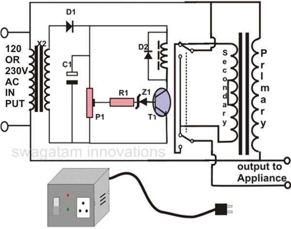
Manual Stepped Voltage Stabilizer Circuit Diagram

Description Here Is The Circuit Diagram Of A Powerful 12v Regulator That Can Deliver Up To 15 A Of Cur Voltage Regulator Circuit Diagram Electronic Schematics

100 Power Supply Circuit Diagram With Pcb Eleccircuit Com Power Supply Circuit Simple Electronic Circuits Electronic Circuit Projects

Automatic Voltage Stabilizer Circuit Diagram Circuit Diagram Circuit Pic Microcontroller

Usb 5v To 1 5v 3v Step Down Converter Circuit Eleccircuit Com Circuit Usb Battery Charger Circuit
How To Make An Automatic Voltage Stabilizer Circuit Construction Explained Bright Hub Engineering

Automatic Voltage Stabilizer Circuit Diagram Circuit Diagram Circuit Diagram

Input voltage circuit the input voltage is generated by a step down transformer is feed to inverting terminal of the op amp as vin.
Manual stepped voltage stabilizer circuit diagram.

Lm350 Voltage Regulator Circuit Diagram Voltage Regulator Electronics Projects Regulators

Solid State Scr Triac Controlled Automatic Voltage Stabilizer Circuit Projects Circuit Electronics Circuit

Voltage Stabilizer Wiring Diagram Automotive Electrical Diagram Bp Oil

How To Use Hall Effect Sensor With Arduino Working Hook Up Guide And Relay Control In 2020 Hall Effect Arduino Sensor
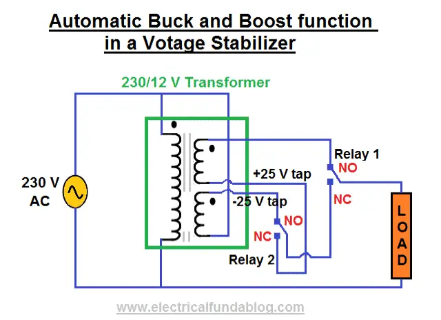
What Is Voltage Stabilizer Why We Need It How It Works Types And Applications

Virtual Ground Regulated And Rail Splitter Circuits Headphone Reviews And Discussion Head Fi Org Circuit Voltage Regulator Current Source

Diy Automatic Solar Charge Controller Solar Circuit Diagram Solar Panels

New Wiring Diagram For Ac Compressor Air Compressor Pressure Switch Exhaust Fan Industrial Refrigerator Compressor

Lcd Tv Repair Guide Lcd Television Lcd Tv Electronics Basics

Lm2596 Pinout Voltage Regulator Electronics Basics Electronic Schematics

1000 Volt Dc To Dc Regulator Circuit Elektronika Transformatory Tokio

How Do You Build A Simple Circuit To Control A Servo Simple Circuit Electronics Circuit Circuit

Buck Converter Working Step 2 Converter Voltage Regulator Inductors

Stepper Motor Driver Using Pic18f4550 Microcontroller Voltage Regulator Microcontrollers Stepper Motor

Simple 12v 1 Amp Smps With Pcb And Transformer Winding Details Carregador Eletronicos Fontes

Schematic Diagram Electronics Basics Circuit Circuit Board

Preher Tech Lcd Tv Repair Guide Lcd Television Lcd Tv Repair Guide

Arduino Interface Mc3479 Stepper Motor Controller Arduino Stepper Motor Steppers
Search Q 12v 12 Volt Regulator Circuit Tbm Isch

Start Run Capacitor Wiring Diagram And Kwikpik Me Motor Circuit 1440 Best Of Starting Electronic Circuit Projects Circuit Projects Water Pump Motor

Lm2576 Buck Converter Pinout Specs Equivalent Circuit Datasheet In 2020 Electronics Basics Electronic Schematics Electronic Circuit Projects

Control Stepping Motor Via Usb Interface Electronic Schematics Electronics Basics Pic Microcontroller

Pin On Energia

Snubber Circuit Design Analysis Electronicsbeliever In 2020 Circuit Design Circuit Analysis
Source : pinterest.com
